JH PCBA MCPCB, Metal Core PCB, IMS (Isolated Metal Substrate)

Manufacture 1-4 Layer aluminum and copper PCB, thermal Conductivity of aluminum PCB: 1- 5w, thermal Conductivity of thermal-electric separation copper PCB: 150W-300W; Special Material: Bergquist, Japan Sumitomo, PTTC, and so on.

What is MCPCB?

Metal core pcb is abbreviated as MCPCB, also named as IMS (Isolated Metal Substrate). It is made of thermal insulating layer, metal plate and metal copper foil, which has special magnetic conductivity, excellent heat dissipation, high mechanical strength and good processing performance.

For metal core base material, there is aluminum and copper base materials. Aluminum substrate is a kind of metal-based copper clad plate with good heat transferring and dissipation function. Copper substrate has better performance than aluminum, but its price is relatively more expensive than aluminum.

Clients order aluminum pcbs more often, because the price of aluminum pcb is much more economic, they are used in cars on indicators, in headlights and brake lights, and other automotive applications, medical equipment high power LED lighting and communication electronic equipment and so on.

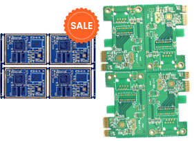
Aluminum PCB with counterbores

Copper PCB with ENIG surface finishing

What kind of MCPCB JH PCBA can provide?

1, MCPCB we can provide as:
   a.Aluminum-based PCB
   b.Copper-based PCB
   c.Ceramic-based PCB
   d.Others: Iron-based PCB

2, Various brand material available:
   ITEQ Bergquist TOTKING Ventec PTTC
   CCAF CHIN-SHI KunShan Uniplus Japan Sumitomo

3, Featured MCPCB JH PCBA can provide:
   a.Thermal-electric separation copper-based pcb: 150W-300W high power miner lamp and streetlight.

   b.COB silver mirror aluminum PCB: after assembly, lights reflectivity up to 98%, luminous efficiency up to 120 LM.
   c.Ceramic-based pcb: thermal conductivity about 26W, withstand high voltage to 8000-10000V.

4,Taiyo white color solder mask used for our MCPCB, with high adhesive force, with high reflectivity, reach 85%.

JH PCBA MCPCB Manufacturing Capability

Type Item Parameter Drawing
manufact ure capacity ayer count: 1-12L /
mixed stackup

FR-4+aluminum substrate

FR-4+copper substrate

/
PCB thickness

aluminum substrate 0.6-5.0mm

copper substrate 0.6-3.0mm

/
thickness tolerance

≤1.0mm: +/-0.10mm,

>.0mm:+/-10%.

/
minimum pcb size 2.5×2.5mm need create panel, 10x10mm cando single board. /
minimum pcb size 500x1200mm /
maximum copper 30z /
manufact ure capacity1 ayer count: 1-12L /
mixed stackup

FR-4+aluminum substrate

FR-4+copper substrate

/
PCB thickness

aluminum substrate 0.6-5.0mm

copper substrate 0.6-3.0mm

/
thickness tolerance

≤1.0mm: +/-0.10mm,

>.0mm:+/-10%.

/
minimum pcb size 2.5×2.5mm need create panel, 10x10mm cando single board. /
minimum pcb size 500x1200mm /
maximum copper 30z /

Material for MCPCB

Material for high
frequency boards
Order share Er, Dk-
permittivity
Dk
Loss Tangent
Tg Td value Thermal
conductivity
CTE-z
(T < Tg)
Electric
Strength
Surace
Resistivity
Peel
strength
@10GHz @10GHz °C °C W/m*K ppm/°C kV/mm MO N/mm
Rogers 4350BHF material +++ 3,5 0,0037 280° 390° 0,69 32 31 5,7 x 10^9 0,9
Rogers 4003CHF material ++ 3,4 0,0027 280° 425° 0,71 46 31 4,2 x 10^9 1,1
Rogers 4003CHF material + 3,6 0,004 185° 410° 45 1 x 10^8 0,8
Panasonic Megtron6HF material + 3 0,0013 500° 0,5 25 1 x 10^7 2,2
Rogers RO3006PTFE ceramic-filled o 6,2 0,002 500° 0,79 24 1 x 10^5 1,2
Rogers RO3010PTFE ceramic-filled o 10 0,0022 500° 0,95 16 1 x 10^5 1,6
Taconic RF-35Ceramic o 3,5* 0,0018* 315° 0,24 64 1,5 x 10^8 1,8
Taconic TLXPTFE o 2,5 0,0019 0,19 135 1 x 10^7 2,1
Rogers RO3001Bonding Film for PTFE 2,3 0,003 160° 0,22 98 1 x 10^9 2,1
Taconic TLCPTFE 3,2 0,24 70 1 x 10^7 2,1

Construction and Manufacturing Process for MCPCB

Single sided 1L Metal Core PCB
Sheet Cutting—Drilling—Circuit—Etch—Solder mask—Silkscreen—Surface Finishing—Forming—Test
Single sided 2L Metal Core PCB
Sheet Cutting(FR4)—Drilling—PTH—Circuit—Plating—Etch—Test—Laminating(FR4+Metal Core)—Solder mask—Silkscreen—Surface—2nd Drilling—Forming—Test
Double sided 2L Metal Core PCB
Sheet Cutting(FR4)—Drilling—PTH—Circuit—Plating—Etch—Test—Laminating(FR4+Metal Core)—Solder mask—Silkscreen—Surface—2nd Drilling—Forming—Test
Double sided 2L Metal Core PCB with insulating holes
Sheeting Cutting—Drilling(Drill resin hole)—plug resin—Laminate(laminate surface copper)—Drilling(Drill actual size hole)—PTH— Circuit—Plating—Etch—Solder mask—Silkscreen—Surface Finishing—2nd Drilling—Forming—Test
Single sided 4L Metal Core PCB, including buried and blind vias
Sheeting Cutting—Drilling(Drill resin hole)—plug resin—Laminate(laminate surface copper)—Drilling(Drill actual size hole)—PTH— Circuit—Plating—Etch—Solder mask—Silkscreen—Surface Finishing—2nd Drilling—Forming—Test
Double sided 4L Metal Core PCB
Sheet Cutting(FR4)*2—Drilling—PTH—Circuit—Plating—Etch—Test—Laminating(FR4+Metal Core)—Solder mask—Silkscreen—Surface—2nd Drilling —Forming—Test

MCPCB Case

Data Acquisition Motherboard

16L 6MM HDI

From $5/10pcsBuild

Time:24 hours

Thick copper high level board

16L 6MM HDI

From $5/10pcsBuild

Time:24 hours

16-layer HDI blind buried hole semiconductor test board

16L 6MM HDI

From $5/10pcsBuild

Time:24 hours

4+2 rigid-soft boards

16L 6MM HDI

From $5/10pcsBuild

Time:24 hours